The Modern Product Design Lifecycle (It’s Not Just CAD)
1. Introduction: The Hardware Startup’s "Valley of Death"
The adage “hardware is hard” has become a cliché in the startup ecosystem, often whispered with a mix of reverence and resignation. However, the difficulty of hardware is not merely a function of physics or supply chain logistics; it is frequently a self-inflicted wound resulting from adherence to antiquated, linear development methodologies. For decades, the industry has relied on a sequential process, often termed “waterfall”, where Industrial Design (ID) hands off to Mechanical Engineering (ME), who then hands off to Manufacturing, who finally hands off to Marketing. This siloed approach creates a perilous “Valley of Death” between the finalization of the design and the validation of the market.
In the traditional model, capital is burned at an alarming rate during the tooling phase, often before a single high-fidelity image has been shown to a potential customer. The tragedy of modern hardware failure is rarely that the product doesn’t work; it is that the product works perfectly but fails to resonate, or conversely, that the product looks beautiful but cannot be manufactured without effectively bankrupting the company through tooling modifications.
As a Design Engineer, I have observed that the most successful hardware companies today are not those with the deepest pockets, but those that have collapsed the barriers between engineering rigor and visual persuasion. They employ an Integrated Lifecycle. This approach leverages Virtual Prototyping (VP) not merely as a visualization trick, but as a core engineering validation tool that runs parallel to CAD development. By integrating tools like Blender, traditionally seen as “artistic” software, into the hardcore mechanical engineering workflow, we can predict aesthetic defects, validate surface continuity, and generate launch-ready marketing assets months before the first steel tool is cut.
This guide explores the systemic shift from linear to integrated product development, dissecting the financial and technical arguments for Virtual Prototyping, and demonstrating how a fusion of engineering and artistry is the only viable path for modern hardware startups.
2. The Linear Fallacy: Why Sequential Design Fails
To understand the necessity of the Integrated Lifecycle, we must first aggressively dismantle the traditional Linear Lifecycle. This model, inherited from legacy automotive and aerospace workflows of the 20th century, separates development into distinct phases with rigid “gates.”
2.1 The "Over-the-Wall" Engineering Problem
In a linear workflow, the Industrial Designer sketches a concept that focuses on ergonomics, aesthetics, and user experience. This concept is then “thrown over the wall” to the Mechanical Engineer. The engineer’s mandate is typically functional: fit the PCB, ensure thermal management, and draft the enclosure for injection molding.

The conflict arises immediately. The engineer, constrained by the reality of component dimensions and manufacturing tolerances, often modifies the external surfaces. A curve becomes flatter to accommodate a battery; a texture is removed because it interferes with the draft angle required for mold ejection. These changes are often made in CAD software like SolidWorks, which uses idealized shading modes (RealView) that mask surface imperfections.
The result is a “Frankenstein” file: a product that functions but has lost the emotional resonance of the original design. Worse, because marketing assets are typically generated after the first physical prototypes (T1 samples) arrive, the marketing team is forced to photograph a product that may not look exactly like the initial promise.
2.2 The Economic Cost of Late-Stage Feedback
The financial implications of the linear model are severe. In hardware development, the cost of making a change increases by an order of magnitude with each phase of the lifecycle, a concept known as the “Rule of Ten.”
|
Development Phase |
Cost to Fix Error |
Time Delay |
|
Concept / Sketch |
$10 – $100 |
Hours |
|
CAD Modeling |
$100 – $1,000 |
Days |
|
Virtual Prototyping |
$1,000 |
Days |
|
Physical Prototyping (3D Print) |
$1,000 – $5,000 |
Weeks |
|
Tooling (Steel Mold) |
$10,000 – $100,000+ |
Months |
|
Production / Market Launch |
$100,000 – $1M+ |
Quarters |
In a linear model, aesthetic validation, checking if the light hits the curve correctly or if the texture looks premium, often happens at the Physical Prototyping or Tooling stage. If a stakeholder decides the device looks “cheap” due to a sink mark or a weird reflection at the T1 sample stage, the startup faces a choice: launch a sub-par product or spend $25,000+ to weld and recut the tool.
Data from the American Society of Mechanical Engineers (ASME) suggests that virtual prototyping can reduce the number of physical prototypes from an average of hundreds (in complex machinery) to as few as one to three. For a lean startup, eliminating even two rounds of physical prototyping can save $10,000 to $50,000 and 8-12 weeks of development time.
3. The Integrated Lifecycle: A Concurrent Approach
The Integrated Lifecycle rejects the baton-pass of the linear model. Instead, it functions as a continuous feedback loop where Design, Engineering, and Visualization happen simultaneously.
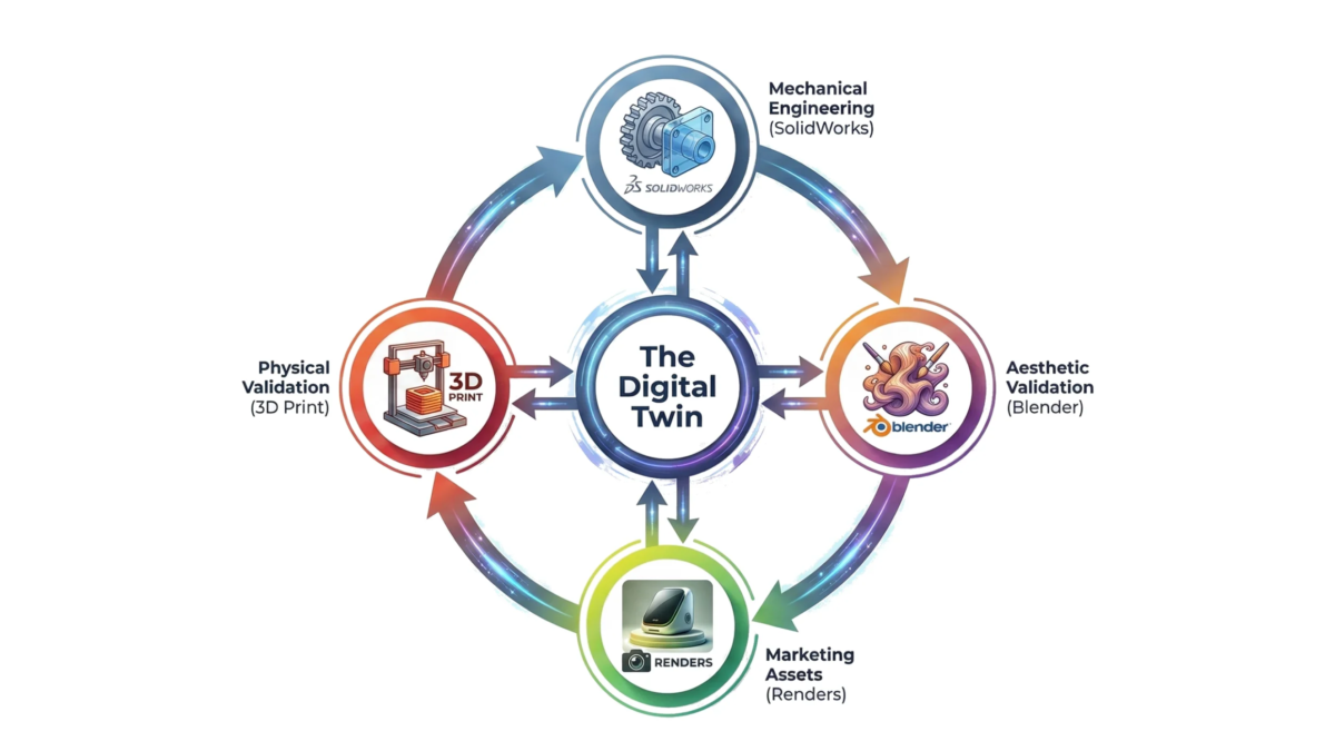
3.1 The Digital Twin as the Source of Truth
In the Integrated Lifecycle, the “Digital Twin” is the central authority. However, this is not just a CAD file. It is a multi-layered asset that exists simultaneously in parametric CAD (for manufacturing) and high-fidelity mesh (for visualization).

When an engineer modifies a rib placement in SolidWorks to improve stiffness, that change is immediately pushed to the Blender artist. The artist updates the render to see if the rib causes a visible sink mark on the exterior surface (simulated through normal maps or displacement). If the render shows an aesthetic defect, the engineer moves the rib before the design is finalized.
This concurrency means that the “Marketing” phase begins on Day 1, not Day 300. We can generate photoreal assets for a Kickstarter campaign or investor deck while the internal ribbing structure is still being debated, provided the external “A-Surface” is defined.
3.2 Strategic Styles: Natural vs. Structured Development
Recent research on hardware product development styles indicates a dichotomy between “Structured” and “Natural” approaches. Structured approaches follow rigid milestones (System Requirements Review, Preliminary Design Review, etc.). “Natural” styles, typified by free-form exploration and iterative prototyping, have been shown to accelerate commercialization, particularly in cleantech and innovative hardware startups.
The Integrated Lifecycle enables this “Natural” style by reducing the penalty of iteration. Because we are iterating in bits (Virtual Prototyping) rather than atoms (Physical Prototyping), we can explore dozens of form factors and CMF (Color, Material, Finish) options in the time it would take to 3D print and sand a single physical model.
4. Deep Dive: Virtual Prototyping as an Engineering Tool
There is a misconception in the engineering community that software like Blender is solely for “pretty pictures” and lacks the precision required for mechanical engineering. This view is obsolete. While Blender is not a parametric CAD tool, you wouldn’t use it to define screw boss tolerances, it is a superior tool for Aesthetic DFM and Surface Continuity Analysis.
4.1 Aesthetic DFM: Predicting Manufacturing Defects
Injection molding is a violent process. Molten plastic is shot into a steel cavity at high pressure and temperature. As it cools, it shrinks. Differential cooling rates cause defects that ruin the visual quality of a product.
- Sink Marks: These occur when a thick section of plastic (like a screw boss or internal rib) cools slower than the thin wall it is attached to. This pulls the surface inward, creating a dimple. In CAD (SolidWorks), the surface looks perfect because the software uses a simplified shader. In a high-fidelity Virtual Prototype, we can apply specific material properties that mimic the refraction of light over uneven surfaces, allowing us to “see” the sink mark before it exists.
- Warping: Long, flat plastic parts are prone to warping. A Virtual Prototype can visually simulate this warpage to determine if the part will look distorted to the consumer.
By identifying these issues in the virtual stage, we can apply engineering fixes (e.g., coring out the rib, reducing wall thickness to 60% of the nominal wall) and re-render to verify the fix.
4.2 Surface Continuity: The Zebra Stripe Test
For consumer electronics, surface quality is paramount. We talk about “Class A” surfaces-surfaces that are perfectly smooth and reflect light without distortion.
- G0 Continuity (Position): The surfaces touch (a sharp edge).
- G1 Continuity (Tangent): The surfaces touch and share a tangent angle (a filleted edge).
- G2 Continuity (Curvature): The surfaces touch, share a tangent, and share the same rate of curvature. This is the standard for Apple-like smoothness.
CAD tools often struggle to visualize G2 continuity effectively in real-time. By exporting the STEP file to Blender and applying a “Zebra Stripe” matcap (a shader that projects alternating black and white stripes onto the object), we can instantly analyze the surface.

If the zebra stripes align perfectly, the surface is smooth. If they zig-zag or break at the seam, the reflection will look distorted on the physical product. Detecting this in Blender allows the engineer to return to the CAD surfacing module and adjust the spline controls, preventing a costly tooling polish later.
4.3 The Blender Workflow for Engineers
The integration of Blender into an engineering workflow requires a specific pipeline to ensure accuracy:
- STEP Export/Import: We export the geometry from SolidWorks/Fusion 360 as a STEP file. This preserves the exact mathematical definition of the curves.
- Tessellation: Using an importer (like MOI3D or specialized Blender addons), we convert the NURBS (mathematical curves) into Polygons. The density of this mesh is critical; it must be high enough to look perfectly smooth but optimized enough to render quickly.
- Normal Transfer: We ensure that the “Custom Normals” from the CAD data are preserved. This ensures that flat surfaces look perfectly flat and curved surfaces look perfectly curved, without the “shading artifacts” common in low-quality 3D models.
- Material Application: We apply physically accurate materials (PBR – Physically Based Rendering). This involves defining the Roughness, Specularity, and Transmission of the plastic, metal, or glass.
This workflow bridges the gap between the “mathematical perfection” of CAD and the “visual reality” of the human eye.
5. The Financial Argument: Reducing Tooling Risk
The most persuasive argument for the Integrated Lifecycle is financial. Let’s break down the costs associated with a typical tooling error, for example, a “parting line mismatch” where the two halves of the mold meet, creating an ugly line on the visible surface of the product.
5.1 Scenario A: The Linear Approach (Fixing in Steel)
- Design is finalized in CAD.
- Tooling is ordered ($30,000).
- T1 Samples arrive 8 weeks later.
- The team realizes the parting line cuts through a critical ergonomic area and looks cheap.
- Action: The tool must be modified. Metal must be welded back onto the mold (if possible) or the cavity must be re-cut.
- Cost: $5,000 – $15,000 in rework costs.6
- Delay: 3-4 weeks for shipping the mold to the toolmaker, machining, and re-sampling.
Total Loss: $15,000 + 1 Month of burned runway.
5.2 Scenario B: The Integrated Approach (Fixing in Pixels)
- Design is drafted in CAD.
- Design is imported to Blender for Virtual Prototyping.
- The artist applies a “Chrome” material which highlights surface imperfections.
- The team sees the parting line reflection is distracting.
- Action: The engineer moves the parting line in CAD to a hidden edge.
- Cost: 2 hours of engineering time (~$300).
- Delay: 0 days (happens concurrently).
- Total Loss: $300.
Insight: The Integrated Lifecycle offers a 50x ROI on risk mitigation for this single issue alone. When compounded across the hundreds of decisions made in a hardware project (texture depth, LED diffusion, color matching, screw placement), the savings are existential.
6. The "Gap" in the Agency Market
Current market solutions for hardware startups are fragmented, forcing founders to act as the integration layer between disparate vendors.
6.1 The Engineering Firm vs. The Design Studio
- The Engineering Firm: Focuses on “Does it work?” Deliverables are STEP files and BOMs (Bill of Materials). Their visualization capabilities are usually limited to screenshot-quality CAD renders which fail to inspire investor confidence or consumer desire.
The Creative Agency: Focuses on “Does it sell?” They create beautiful images, often by modeling the product from scratch in 3D software (Maya/Cinema4D). However, these models are often “geometry-light”, they look good but are dimensionally inaccurate and cannot be manufactured. A startup often ends up with a marketing image that promises a thin bezel, only to deliver a thick bezel because the creative agency didn’t account for the LCD driver stack.
6.2 The Competitor Gap
There is a distinct lack of agencies that bridge this divide. A “Competitor Gap Analysis” reveals that most firms are either “Technical-First” (ignoring aesthetics) or “Visual-First” (ignoring physics). This bifurcation creates the “Execution Gap”, where the product promised in the Kickstarter video differs significantly from the product delivered to backers. This discrepancy leads to high return rates, brand damage, and failed launches.
6.3 The "RAD" Advantage
The solution and the ethos of The RAD Workshop is to house both competencies under one roof. By having the Blender Artist sit next to the Design Engineer (virtually or physically), the feedback loop is instantaneous. The marketing assets are the engineering validation. The Kickstarter video isn’t a lie; it’s a high-fidelity simulation of the actual CAD data that is being sent to the factory. This integrity builds trust, and trust is the currency of the hardware startup.
7. Conclusion: Iterate in Bits, Deliver in Atoms
The era of “launch and pray” is over. The hardware startups that survive the next decade will be those that treat visualization as an engineering discipline.
By adopting the Modern Product Design Lifecycle, you are not just getting pretty pictures. You are getting:
- Risk Mitigation: Seeing defects before they are cut into steel.
- Speed: Launching marketing campaigns months earlier.
- Capital Efficiency: Reducing physical prototypes and tooling rework.
- Cohesion: Ensuring the product you sell is the product you build.
The Integrated Lifecycle is not a luxury; it is a prerequisite for modern manufacturing agility. It turns the “Valley of Death” into a bridge, allowing you to cross from concept to commercialization with your budget and your vision intact.